

")
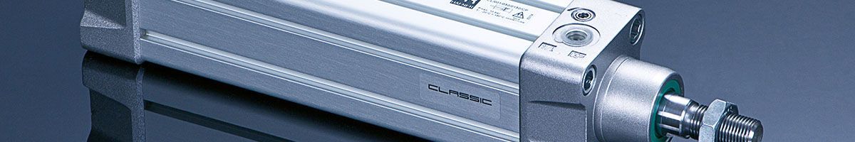
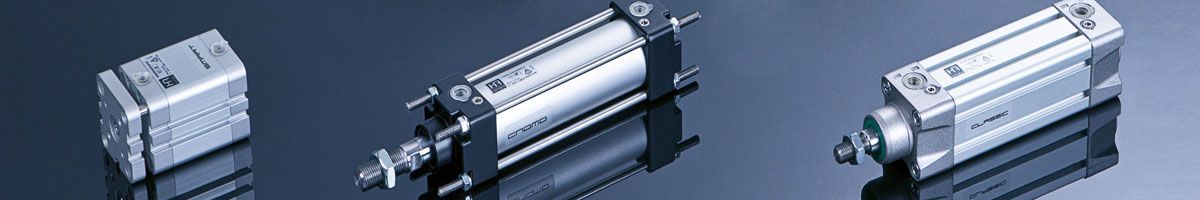

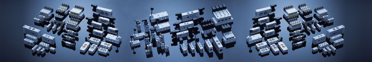
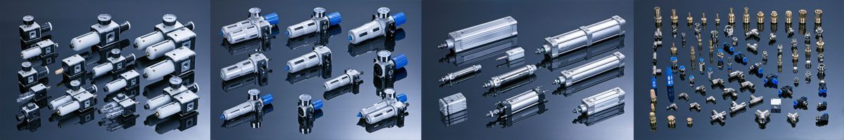
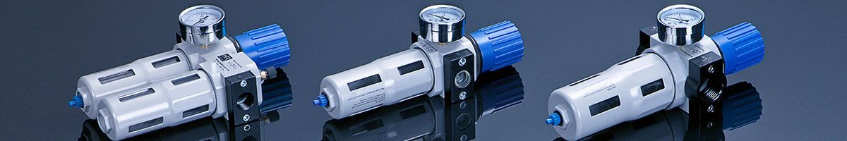

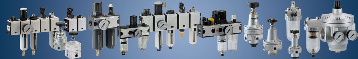

Pneumatics, Compressors, Dryers, Tanks, Pneumatic installations, Air prepration units, Gauges, Pneumatic tubes, Pneumatic valves, Pneumatic cylinders, Pneumatic fittings.
Flow regulation valves – spool valves
1. Basic Information
Directional control valves of the working medium flow is divided into the following groups:
- Valves
- Check valves
- Drain Valves
- Valves logical
- Shut-off valves
1.1 Valves
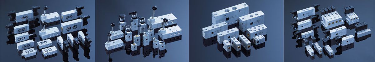
Spool valves (valves), are a group of pneumatic components, whose job is to control the flow direction of the working medium in the pneumatic drive systems and control by combining or switching flow paths. Changing the direction of flow depends on the design of the spool valve slider, a separating plate (for mechanical valves) or the plug.
The pneumatic control systems are used to implement displacement cylinders (cylinders pneumatic linear and rotary or reciprocating), stopping the cylinder at a specific position of the control system, regulatory, and logical. An example diagram of the pneumatic cylinders are listed below.
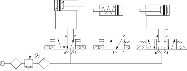
An example of the control actuators bilateral and unilateral action using a valve 5/2 and 3/2.
Graphic symbols of the spool valves
Spool valves for technical drawings and construction documents are presented in the form of graphic symbols in accordance with PN-EN ISO 3952-1: 1998. Graphical symbols contain information about the number of roads, the amount of valve positions, the method and the control varieties. Producers on the nameplates of products also put graphic symbols in order to identify them.
Graphic symbols are given in a full or simplified form. Both forms allow for identification of the spool valve type, however the full form, in some cases, allowes for better specyfication of functional properties of spool valve.
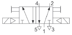
SIMPLIFIED SYMBOL
Simplified diagram of 5/2 spool valve, controlled electromagnetically indirectly.
Complete and accurate draw of the symbol of the simplified spool valve 5/2 driven electromagnetically indirectly.
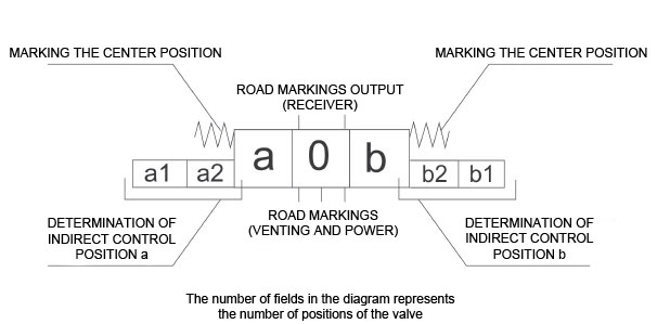
Rules of creating the graphic symbols for the typical spool valves
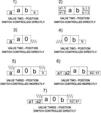
Oznaczenia na rysunkach:
Designations descriptions letter located on the symbols above:
0 - initial position
a, b - position of control or control these positions,
a1, b1 - the first degree of control valve
a2, b2 and - controlling the second stage of the valve,
a1.1, a1.2, b1.1, b2.2 - marking direct control valve or control of the first degree.
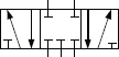
Examples of graphic symbols of valves without marking method their control of typical connections of internal roads.
| Graphic symbol | Function description |
| Spool valve 2/2 normally closed | |
 |
Spool valve 2/2 normally open |
| Bilateral spool valve 2/2 normally closed | |
| Bilateral spool valve 2/2 normally open | |
| Spool valve 3/2 normally closed | |
 |
Spool valve 3/2 normally open |
 |
Bilateral spool valve 3/2 normally closed, normally open |
 |
Valve 5/2 |
 |
Valve 4/2 |
 |
Valve 5/3 in a central position, current connected receivers |
 |
Valve 5/3 in a central position, vented receivers (connected to the atmosphere) |
 |
Valve 5/3 in a central position, all ways cut off |
Table with the typical markings of pneumatic control
| No | Graphic symbol | Function description |
| 1 | Controlled by push-button (poppet) | |
| 2 | Button-controlled | |
| 3 |  |
Controlled by lever |
| 4 |  |
Pedal-operated |
| 5 | Controlled pusher (mechanical) | |
| 6 | Spring controlled | |
| 7 | Controlled by roller (bi-directional) | |
| 8 | Controlled by roller broken (one-way) | |
| 9 | electrically controlled | |
| 10 | Pneumatically controlled (air-pressure increase) | |
| 11 | Controlled by pressure (pneumatically by pressure drop) |
Spool valves are characterized by:
1) The number of respiratory flow.
2) The number of controlled positions of the flow control element.
3) Valve size (volume flow by way of the valve).
4) A control method.
5) Variety of control.
6) The method of supply (by wire or by connecting plates).
Number of working medium flow path:
Spool valves due to the amount of the flow passages are divided into:
- 2 - ways,
- 3 - ways,
- 4 - ways,
- 5 - ways
Flow path in the valves are marked with numerals separation where:
- 1 – way power,
- 2, 4 – way receivers
- 3, 5 – road vent.
The number of controlled positions of the flow control element:
There spool valves:
- 2-position
- 3-position
- tilting X.
For valves 3-position distinguishes between different varieties of the central position of the valve. They are: all roads cut off, the receivers connected to the power supply, receivers connected to the atmosphere
Valve size.
The size of the valve is commonly known as the connecting thread size located in the valve body, or sometimes sub-bases and parts of the island where the valve can be mounted in the valve. Valve size is commonly identified with the size of the working medium flow through the diverter valve.
In the pneumatics, the most common sizes of threads inch pipe are in the range from G1 / 8 'to G2', in case of valves with small size, it is common to find metric threads in size range from M3 to M6. Untypical control elements of the flow direction of the working medium have threads other than those mentioned above. In some materials, catalog value is given DN (nominal diameter), which is the diameter of the hole through which the air flow occurs.
A control method.
Control method specifies a method for moving the splitter (usually a slider) implementing change positions of the flow passages of the spool valve. There are the following ways to control spool valves:
- solenoid (electrical)
- pneumatic control (through an increase or decrease in pressure)
- mechanical control
- control in a mixed way
Variety of control
Due to the variety of control spool valves are divided into:
- controlled directly
- controlled indirectly.
The directly controlled valves (solenoid controlled) working movement of the slider is forced by the plunger of the electromagnet, which is connected to the slider. Direct control of valves usually affects small flow rates and electromagnetically-controlled shut-off valves for low pressure. This is because the application of high power solenoid coils needed to produce the required force needed to overcome the resistance of movement of the separation element and the working medium pressure.
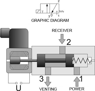
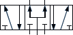
Graphic diagram of spool valve 3/2 controlled directly with the electromagnet , return by spring
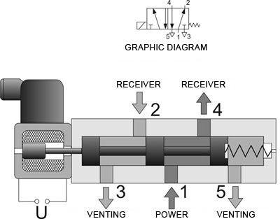
Graphic diagram of spool valve 5/2 controlled directly with the electromagnet , return by spring
The advantage of direct control is quick action valves, no contact working medium with the internal elements of the electromagnets and the simplicity of the design.
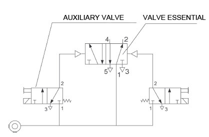
Pilot operated spool valves is carried out using an additional auxiliary valve is often referred to as 'pilot' (controlled in a direct manner), the electrical signal to the overload pressure of the working head on the active surface of the primary valve spool, causing the displacement. Normally it is used also additional mechanical control in the form of the auxiliary valve allowing the valve to stroke without giving an electrical signal.
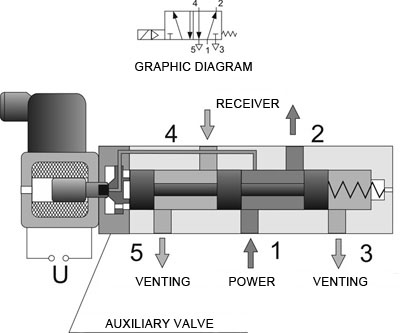
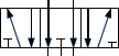
Graphic diagram of spool valve 5/2 controlled indirectly with the internal supply auxiliary valve channel 1.
Air pressure to override the auxiliary valve may be provided directly from the supply channel 1 liners made in the valve body or slider (called. Controlling self or internal pressure). It can also be administered externally via port in the valve or the subbase. Such control is called foreign control. After clipping the electrical signal of the auxiliary valve, the air pressure is applied to the surface of the slider, and the resulting force causes the movement and change of the internal connection flow paths. In order to increase the air pressure overload often can not be applied directly to the slide, but the additional piston with a larger diameter than the slider, and this only causes a movement of the slider. Such valves are called assisted pneumatic valves.
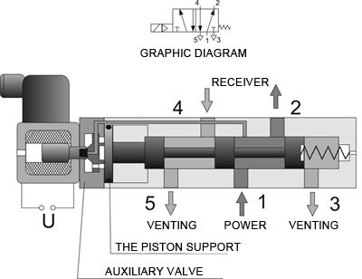
Graphic diagram of spool valve 5/2 controlled electrically with pneumatic support.
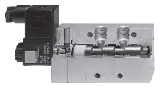
Cross-section of a typical spool valve controlled 5/2 electro-pneumatic back.
The return of the spool valve spool to its initial position caused by the forces is carried out:
- spring
- air pressure acting on the slider
- air pressure acting on the additional piston
- air pressure applied to the slider and the spring force.
The advantage is the ability to control intermediate valve control large flow volumes using a low power solenoids.
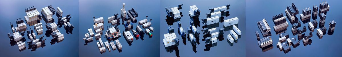
Power Method.
Because of the way the power spool valves are wired versions and labels. The valves have threaded holes wire supply, exhaust and receivers - made bodies. These are usually threads inch from G1 / 8 'to G3 / 4'. There are non-standard implementation of valves with other threads (metric, inch tapered, etc..)
Plate valves are mounted through appropriate individual or valve plates composed of teams. Typically, plate valves have a high flow rate. Currently, commonly used valve islands consist of a large number of valves mounted on the disc, which offers an additional electrical connectors.
The advantages of plate solutions include:
- fast assembly and disassembly without removing the valve pneumatic system
- limiting the number of fasteners and wires
- possibility of installation in confined spaces
- integration of pneumatic control electronics
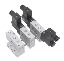
Modular valve terminal
1.2 Return valves
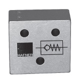
The check valve is used to achieve the working medium flow in only one direction, the opposite direction flow of the fluid is blocked. The valve operates automatically and does not require any additional signals. For the valve due to its construction it is essential minimum opening pressure, which should be as small as possible.
There is a variation of this type of valve called a controlled valve, wherein by introducing additional external signal may be the 'opening' for the working medium flow in the opposite direction.
1.3 Logic valves
Logic valves : sum and difference
These are valves used in pneumatic control systems and regulators to implement logic functions. The most commonly used product valves and valves sum, which allow the construction of pneumatic combinational and sequential.
1.4 Zawory odcinające
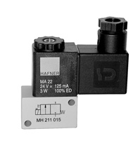
Electromagnetically-controlled shut-off valve
Group electromagnetically actuated valves, pneumatically and mechanically about the features of 2.2, 3.2 used for cutting and opening of roads flow. The working fluid can be compressed air, gases, steam, hydraulic oil or water. Sensitive is also an additional function: the valve normally closed (NC or called. NC) and normally open (NO), which is in what position the valve is no signal
2. Compressed air flow control valves
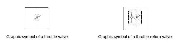
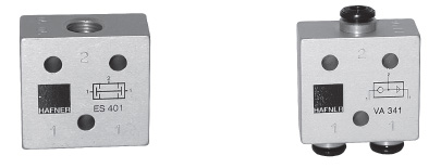
Flow control valves are used in pneumatic systems mainly for variable speed motion actuators (cylinders linear and rotary). To adjust the speed of movement of the piston rod are used throttle valves, check valves and throttle valves. Throttle – return valves allow for free movement of the working medium in one direction, and adjust throttling of the flow in the opposite direction. Throttle valves are bi-directional valves, throttling takes place in both directions of flow.
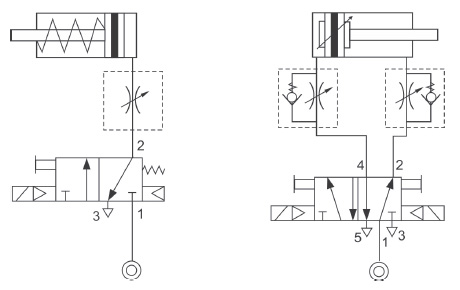
Examples of the use of flow control valves to regulate air traffic speed and double-rod cylinders single acting.
Due to the effectiveness of the choke return valves should be installed as close to the actuator due to the minimization of the volume of pollutants. Due to the compressibility of the working medium for the most efficient speed control cylinders is obtained choking the flow of air on the outlet side of the actuator chamber. It is used the movement speed of the cylinder in both directions or only in one direction.
The Design Departament

General Pneumatics

A Reliable company

General trade conditions

ABOUT US
Pomagier-Trzebuchowscy
sp. z o.o.
ul. Marii Skłodowskiej-Curie 97
87-100 Toruń
NIP 556-22-23-819
Regon 092307860
KRS 0000154149
Santander Bank Polska SA
79 10901069 0000 0000 0704 8941
Bank account ING Bank Śląski
64 10501139 1000 0023 4975 0618
CSP
Fundusz Europejski

News
We have become part of the Rubix Group
Hafner w czasie pandemii

Generatory azotu

Siłowniki dla hutnictwa
CSP

Cylinders production