

")

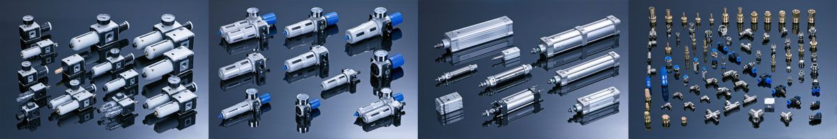
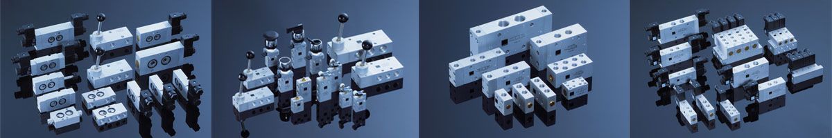
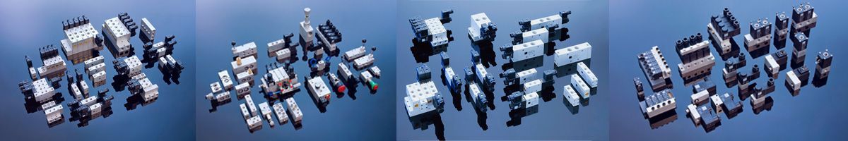
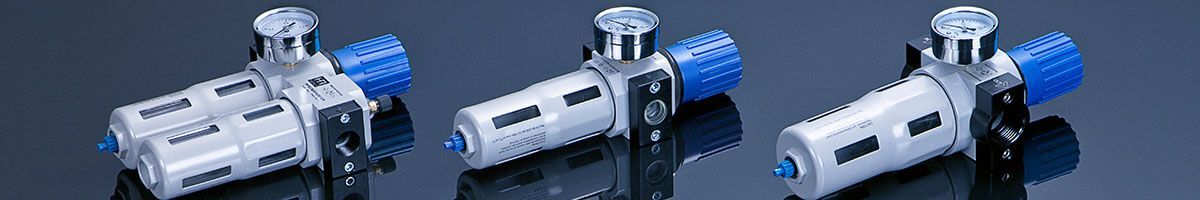

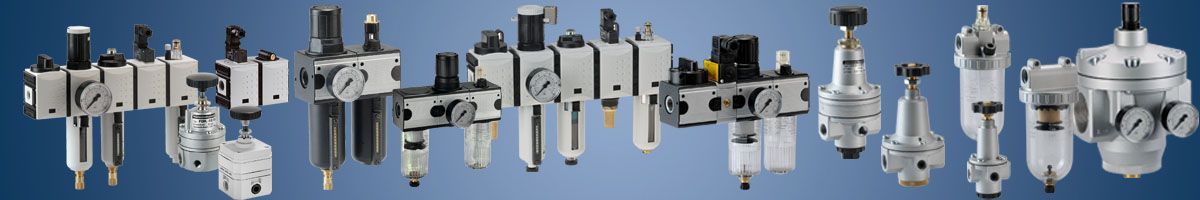

Pneumatics, Compressors, Dryers, Tanks, Pneumatic installations, Air prepration units, Gauges, Pneumatic tubes, Pneumatic valves, Pneumatic cylinders, Pneumatic fittings.
Articles
Wytwarzanie sprężonego powietrza
Manufacturing of the compressed air
The compressed air is produced by compressors. The compressor is a device, which increases the pressure of the working medium above the starting pressure – which is said to be the atmospheric pressure. According to the definition and compressor’s construction features, compressors can be divided into two groups:
- Positive displacement compressors
- Flow compressors.
In the positive displacement compressors the pressure increase is by suction and pressing the gas volume in the form of successive portions of the item in part driven. Compression of the air is done in the enclosed volume. Due to the type movement which is executed by the displacement element, the compressor can be divided into:
- sliding-return motion compressors (piston)
- rotary motion compressors (vane, toothed, rotary).
Please see below, the most common types of compressors
1. Piston compressors
It is one of the most common groups of the compressors used to make the compressed air in the industrial installations. They are dedicated to produce the output pressures in the range from 0,1 MPa (1 bar) up to more than a dozen MPa (tens of bar).
Mobility element of these compressors is the driven piston which does the sliding- return motion and thanks to it , it draws the atmospheric air, compresses it and then sends to the stamping area. The construction of the piston compressor is given below:
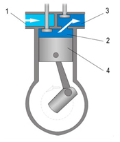
1 - suction chamber
2 - working chamber
3 - stamping area
4 - piston
2. Positive displacement – diaphragm compressors
Diaphragm compressors, are also called diaphragm flaps. They are equipped with a moving piston, which moves diaphragm air compression. It is separated from the compression chamber. There is no direct contact with the compressed air, thus it is not contaminated with the oil used to lubricate the piston. These compressors are used where very high grade of air purity is required- for example: pharmaceutical industry, food industry chemical industry, etc. The construction of the compressor is shown in the following diagram:
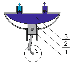
1 - Piston
2 - Diaphragm
3 - Compression chamber
3. Rotary displacement compressors
Rotary displacement compressors are classified according to the number of shafts. There are compressors with one shaft, two shafts or more shafts. The operating principle of rotary compressors is compressed portion of the gas in the working areas of variable volume. Rotary Displacement compressors are divided into:
- screw compressors
- vane compressors
- Root’s compressors
- compressors with rotary piston
- compressors with water ring
4. Rotary screw compressors
The rotary screw compressors are devices, that are dedicated for producing compressed air on the two rotating shafts. Rollers have a profile with screws and are asymmetric one to another. The principle of operation is based on the formation of the inner chambers, wherein the compression of air between the two rotors is screw-shaped. The air in the chamber moves from the suction side to the discharge channel.
The main advantages of screw compressors are:
- high performance
- the absence of the flow and pressure pulsations
- ability to work in 24h
- constant flow and pressure at the outlet
- thermal energy recovery
- quiet operation
- Full control over parameters and working time
- low power consumption
- through the formation of an oil film between cooperating rotors there is no direct contact area, which increases the durability of the device
The figure below shows the principle of a screw compressor
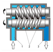
1 - Inlet channel
2 - asymmetrical screw rotors
3 - channel pumping
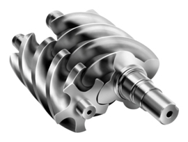
Screw team
5. Root’s compressors – centrifugal
This compressors fulfills the role of elements of the two motors driven by the rotor profile. A characteristic of this type of compressor is that the air moves from the inlet to the outlet without a change in volume. Working space has the shape of cooperating cam-shaped rotor, the space on the inlet side is increased to allow air suction. From the pressure side decreases in volume to compress the air. The diagram below shows the construction of the compressor.
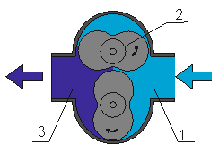
1 - suction chamber
2 - shaped rotors
3 - pumping chamber
6. Reciprocating displacement vane
A compressor, wherein the pressure increase takes place in the shrinking chamber as a space formed between the slidably mounted on the rotor blades and the compressor housing. The axis of rotor blades is mounted eccentrically offset relative to the axis of the body. During the movement of the rotor blades centrifugal force presses the sides of the body sealing working chambers, which, together with the trade to reduce its volume compress air discharge side. The increasing displacement from the suction side allows air intake. The following diagram illustrates the operation of the compressor vane.
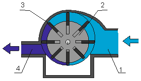
1 - suction channel
2 - eccentric rotor
3 - movable vanes
4 - channel virgin
The biggest advantages of vane compressors:
- quiet, devoid of emotion work
- high purity of the obtained compressed air
- simple, easy to repair and maintenance construction
- the possibility of continuous operation in cycles of 24 hours at a stabilized temperature
- lack of ball bearings, which can generate noise and are subject to wear
7. Screw flow compressor
Compressors working on the principle of flow of the air flow and their construction are used in the systems or devices requiring a very high flow rate (expense). They are characterized by the relatively low pressure at the outlet. Air compressor element is rotating at a high speed rotor, which causes the geometry of the vacuum from the suction air. Screw flow compressors are divided into two groups: the turbocharger, wherein the movable member is shaped rotor blades and the jet compressor.
The Design Departament
General Pneumatics

A Reliable company

General trade conditions

ABOUT US
Pomagier-Trzebuchowscy
sp. z o.o.
ul. Marii Skłodowskiej-Curie 97
87-100 Toruń
NIP 556-22-23-819
Regon 092307860
KRS 0000154149
Santander Bank Polska SA
79 10901069 0000 0000 0704 8941
Bank account ING Bank Śląski
64 10501139 1000 0023 4975 0618
CSP
Fundusz Europejski

News
We have become part of the Rubix Group
Hafner w czasie pandemii

Generatory azotu

Siłowniki dla hutnictwa
CSP

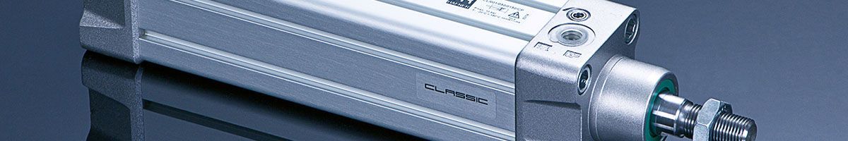
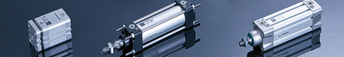
Cylinders production