

")


Pneumatics, Compressors, Dryers, Tanks, Pneumatic installations, Air prepration units, Gauges, Pneumatic tubes, Pneumatic valves, Pneumatic cylinders, Pneumatic fittings.
Articles
Przygotowanie sprężonego powietrza
Preparation of compressed air
1. Basic information
The first pneumatic elements are located directly after compressors and are the air preparation units elements. They are used to prepare the working medium, necessary for the proper operation of pneumatic components:
- clearing - (filtration) from the solid particles, particles of oil condensate water - filter
- reduction (adjusting) pressure to the required level of working - pressure-reducing valves
- covering with mist - lubricators.
Preparation of compressed air is carried out to enhance the stability of pneumatic components, extending the service life of the controls and regulations. Reduction of component failure is achieved by lubrication of the moving parts and sealing:
Particulates - entering the compressed air through the compressor to the intake air from the environment. They remain in the devices of compressed air (as well as pipes and installations). These particles are released through physic-chemical (corrosion, scale, particle aging and damaged seals) or mechanical due to wear of moving parts in the compressor or other pneumatic components included in the system.
Oil - coming from the compressor (mainly the construction of the piston), or in the form of debris, entrained by the air flow from the walls of the ducts. The oil in the form of droplets may also precipitate in the form of condensate in the case of intentional pneumatic lubrication oil mist.
Water - in a natural manner is dissolved in the form of water vapor sucked in through the outside air compressor. Water can also enter the compressed air tanks are placed for the compressors. The amount of water contained in the working medium of the air temperature and relative humidity.
2. Methods
2.1 Filtration
Filtration of the compressed air takes place in a filter that removes particles primarily. They are filtered by the filter element with the specified accuracy of purification. As the standard of cleaning shall be 40 µm, which is equivalent to 5th grade purity compressed air and it is sufficient for the correct operation of pneumatic fittings. In the case of precision pneumatic components filtration accuracy should be 5µm, which, according to ISO 8573-1: 2010, is the 3 air cleanliness class. Standard filters also remove precipitated by expanding the working fluid in liquid water. They also remove larger particles of oil. Thanks to the centrifugal force of whirling stream, bigger participles are disposed on the inner surface of the tanks. Below is a table with compressed air quality classes.
| Class according to ISO 8573-1 | The maximum size of particles [µm] | The maximum concentration of particles [mg/m²] | The maximum value of the pressure dew point [°C] | The maximum oil concentration [mg/m²] | The maximum content of H2O [g/m³] |
| I | 0,1 | 0,1 | -70 | 0,01 | 0,003 |
| II | 1 | 1 | -40 | 0,1 | 0,12 |
| III | 5 | 5 | -20 | 1 | 0,88 |
| IV | 15 | 8 | +3 | 5 | 6,0 |
| V | 40 | 10 | +7 | 25 | 7,75 |
| VI | +10 | 9,4 |
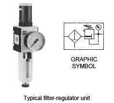
The figure below shows the construction of a typical filter used for rough air purification.
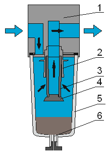
The filter is made from the body (1) which is built into the holes - the power and exhaust. Air enters the filter in accordance with the arrows and is directed downwards, where the drive (2) causes swirling air stream and expands, thus precipitating the water contained in the air. The centrifugal force throws the walls of the tank (5) higher suspended solids (oil condensate droplets, water droplets, particles) that accumulate on the bottom of the tank in the form of condensate. The air flows through the cartridge filtering (3), and is treated with minor impurities (in Dependency on the accuracy of filtering). Is then directed to the outlet and downstream parts of the system. Filters are equipped condensate discharge valves(6), which can operate manually, semi-automatically or automatically.
In order to protect the tank against mechanical damage, mounting the cover is recommended.
Manual releases are activated by screwing or pressing the stopper. Semi-automatic vent valves utilize the pressure drop across the valve element for opening and ejecting the condensate. Fully automatic drains are equipped with a float valve which is being opened when the target level of condensate in the tank is exceeded.
In accordance with the applicable provisions of the condensate is drained from the filters, oil molecules must be subjected to a purification process before being discharged to the sewer.
2.2 Oil separation
The oil contained in the working medium is removed in an oil separator. The condensate oil and water may also be removed to some extent in the filters, but it is not a complete removal. Oil free operating medium is particularly important in some industries, such as food, pharmaceutical, varnishing and medicine. It is also not a desirable in precision industrial automation systems.
Further purification steps of compressed air :
- Pre-filtering the air through filters - traps in which the separation of the oil droplets by centrifugal precipitation of the walls of the device. This method allows you to clean the air only with large concentrations of oil particles.
- Filtration with a first-class cleanliness.
- Filtration with activated carbon filters.
In order to optimize operating costs of precision oil separators should be installed in front of them coarse filters.
2.3 Drainage of the working medium
Preliminary and necessary for the proper operation of components and systems, pneumatic removal of water is done by filters. Precise removal of water from the working medium, which is required in some applications is accomplished through dehumidifiers, which use physical and chemical phenomena. (dryers, cyclones, absorption, Refrigeration).
This phase is the biggest contributor to ensuring a level of preparedness adeqately working medium. Precipitating water in the pneumatic systems is the cause of many disturbances and failures. The following are the most important reasons for failure:
- Corrosion causing secondary pollution principles permanent and debilitating design and installation of pneumatic equipment,
- Reducing the active section of the channels in the elements of air and increasing the air friction of the corroded surface,
- Leaching of solid lubricants with moving parts, pneumatic equipment causing the excessive wear or failures.
In addition to the use of specialized equipment to remove water, you can already at the stage of system design avoid excessive accumulation of water. Below are some practical methods:
- Pneumatic systems should be performed at a small angle rising, so that condensed water running down to the lowest point, there will be discharged to the outside. ,
- Departures (pions) from the main system should be operated only from the top of the power cord, which prevents the already precipitated condensate receivers,
- Use traps cyclone not only for the compressor or air tank, but also against any receiver,
- Use high pressure reductions compared to the supply pressure.
2.4 Reduction (adjustable) pressure working medium

The regulator compressed air
To reduce the pressure in the pneumatic systems to the required level applies pressure reducers. These valves belonging to the group of elements pneumatic control pressure (usually adjustable manually), whose task is to maintain a constant pressure of the working medium at the output, regardless of changes in the higher inlet pressure regardless of changes in the rate of flow through the valve.
Elements of reducing pressure to the required level are divided into the following groups:
- Direct action
- Second control pressure:
- The internal pressure of the reference ,
- The internal pressure of the reference,
- Components:
- With solenoid valves ,
- Piezo valves
Below is a diagram of a typical pressure-reducing valve spring structure.
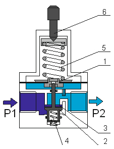
The operating principle is based on cutting off the supply chamber, in which there is a supply pressure P1 from chamber starting with the poppet valve (2) closing the valve seat (3). The armature is at the top, through a force of the pusher spring (5) tensioned by rotation of the adjusting screw. Poppet valve without shutoff of this force is the force of the spring into the slot (4). Realizing valve opening by downward movement of the diaphragm assembly and causes air to flow into the output chamber (for a poppet valve) and increase the pressure P2 in the chamber to a value dependent on the strength of the spring tension. The output pressure is also supplied to the chamber beneath the membrane (1). The increase in pressure P2 increases the force counteracting the force of the opening spring valve, until its closure, or the establishment of such an intermediate position at which the output pressure will stabilize and the balance force of the spring adjusting. Tight the control spring (5) using the screw (6) to change the valve opening force, which shall be submitted on change in the value of reduced output pressure P2. By reducing the pressure to atmospheric pressure the valve vents the excess pressure drops to atmospheric. P2 pressure at the outlet of the valve does not change when changing the supply pressure P1. The catalogs for pressure reducing valves are always served operating characteristics: regulatory and flow. Regulatory characteristics determines the output pressure changes in relation to the inlet pressure and flow rate determines the air flow through the valve at a predetermined pressure drop reduced value P2.
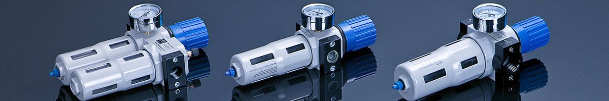
Commonly used a single unit of two components: the filter and the pressure reducing valve. This element is called band filter-regulator or valve-filter. This is the first element where the air is cleaned and then the cleaned air flows into the pressure reducing valve, where the pressure reduction to the working pressure.
2.5 Lubrication of the compressed air
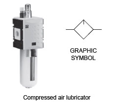
In the pneumatic systems there are elements, that are responsible for forming the friction kinematic pairs (eg. Piston - sleeve, piston rod - guide sleeve in the pneumatic cylinder). To make sure that the device operates correctly it must be lubricated with oil. Lubricated air is also required for pneumatic tools such as hammers, drills, screwdrivers, grinders, where all elements move at very high speeds and are driven by pneumatic turbines.
Lubrication of the compressed air is the introduction to the working medium of oil particles in the form of mist, which reached to the cylinders and control lubrication of the moving parts. This prevents faults and failures, further prolonging their service life and reducing the incidence of corrosion. Generating elements are oil mist lubricators compressed air. In modern construction solutions used seals made of polyurethane (PU).Cylinders with seals of this material do not require lubrication with oil mist.
Lubricators, because of their structure are divided into the following groups:
- drinkers,
- selection,
- wick,
- injection,
- vesicular.
The most common are the nipple lubricators.
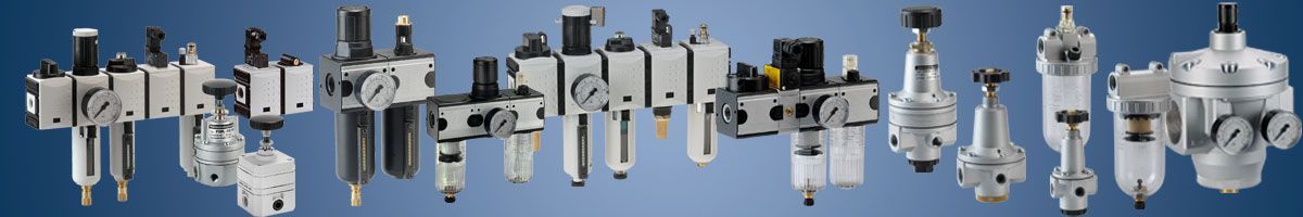
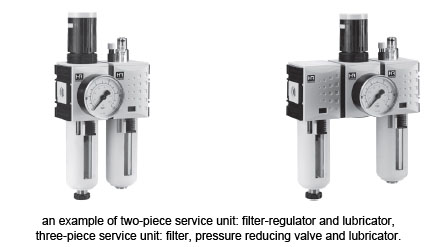
Their principle is based on the phenomenon of drop in pressure in the lubricator gun nozzle, which draws a drop of oil from the reservoir through the tube, droplet chamber, where oil droplets are broken up into a stream of compressed air and oil mist then introduced into the pneumatic system. These elements of the air preparation system appears individually, or more frequently as air preparation units or power stations. Then they consist of two or three components:
- two-piece service unit: filter-regulator and lubricator,
- three-piece service unit: filter, pressure reducing valve and lubricator.
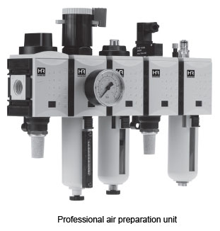
Professional air preparation units are understood as a complex elements of air preparation units which may include additional equipment needed to supply the modern pneumatic systems. These can be manually controlled shut-off valves or solenoids, valves slow start (the so-called. Soft-start), pneumo-electric relays, pressure gauges, flow meters and pressure displays and outputs for drivers. This results in extending the functionality of a typical air handling units.
The Design Departament

General Pneumatics

A Reliable company

General trade conditions

ABOUT US
Pomagier-Trzebuchowscy
sp. z o.o.
ul. Marii Skłodowskiej-Curie 97
87-100 Toruń
NIP 556-22-23-819
Regon 092307860
KRS 0000154149
Santander Bank Polska SA
79 10901069 0000 0000 0704 8941
Bank account ING Bank Śląski
64 10501139 1000 0023 4975 0618
CSP
Fundusz Europejski

News
We have become part of the Rubix Group
Hafner w czasie pandemii

Generatory azotu

Siłowniki dla hutnictwa
CSP

Cylinders production