

")


Pneumatics, Compressors, Dryers, Tanks, Pneumatic installations, Air prepration units, Gauges, Pneumatic tubes, Pneumatic valves, Pneumatic cylinders, Pneumatic fittings.
Flow regulation valves – spool valves
1. Basic Information
Directional control valves of the working medium flow is divided into the following groups:
- Valves
- Check valves
- Drain Valves
- Valves logical
- Shut-off valves
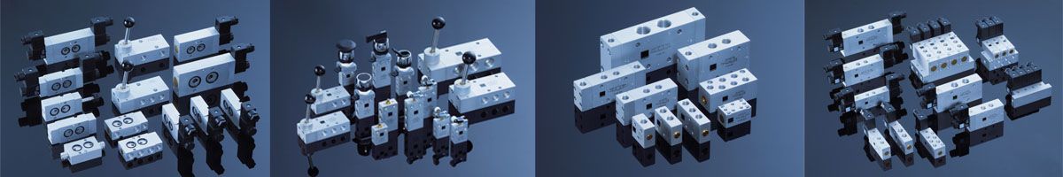
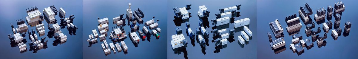
1.1 Valves
Spool valves (valves), are a group of pneumatic components, whose job is to control the flow direction of the working medium in the pneumatic drive systems and control by combining or switching flow paths. Changing the direction of flow depends on the design of the spool valve slider, a separating plate (for mechanical valves) or the plug.
The pneumatic control systems are used to implement displacement cylinders (cylinders pneumatic linear and rotary or reciprocating), stopping the cylinder at a specific position of the control system, regulatory, and logical. An example diagram of the pneumatic cylinders are listed below.
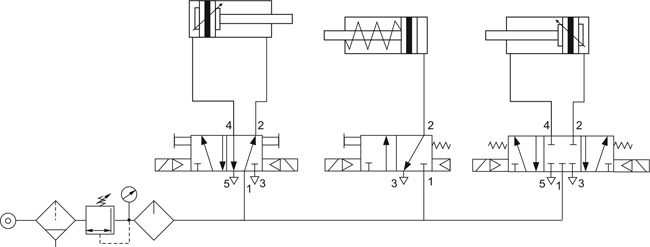
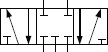
An example of the control actuators bilateral and unilateral action using a valve 5/2 and 3/2.
Graphic symbols of the spool valves
Spool valves for technical drawings and construction documents are presented in the form of graphic symbols in accordance with PN-EN ISO 3952-1: 1998. Graphical symbols contain information about the number of roads, the amount of valve positions, the method and the control varieties. Producers on the nameplates of products also put graphic symbols in order to identify them.
Graphic symbols are given in a full or simplified form. Both forms allow for identification of the spool valve type, however the full form, in some cases, allowes for better specyfication of functional properties of spool valve.
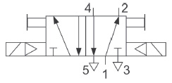
SIMPLIFIED SYMBOL
Simplified diagram of 5/2 spool valve, controlled electromagnetically indirectly.
Complete and accurate draw of the symbol of the simplified spool valve 5/2 driven electromagnetically indirectly.
Rules of creating the graphic symbols for the typical spool valves
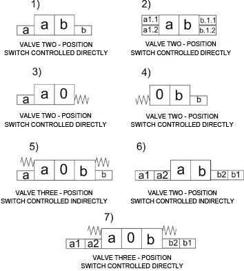
Oznaczenia na rysunkach:
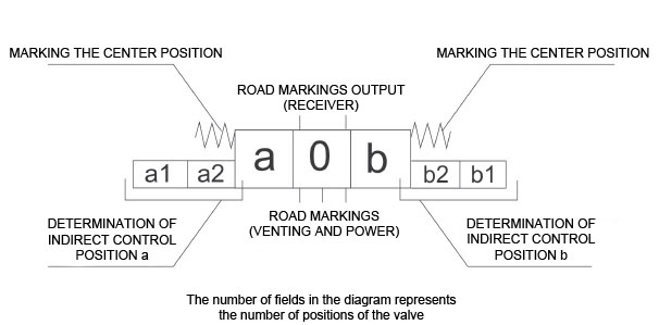
Designations descriptions letter located on the symbols above:
0 - initial position
a, b - position of control or control these positions,
a1, b1 - the first degree of control valve
a2, b2 and - controlling the second stage of the valve,
a1.1, a1.2, b1.1, b2.2 - marking direct control valve or control of the first degree.
Examples of graphic symbols of valves without marking method their control of typical connections of internal roads.
| Graphic symbol | Function description |
| Spool valve 2/2 normally closed | |
 |
Spool valve 2/2 normally open |
| Bilateral spool valve 2/2 normally closed | |
| Bilateral spool valve 2/2 normally open | |
| Spool valve 3/2 normally closed | |
 |
Spool valve 3/2 normally open |
 |
Bilateral spool valve 3/2 normally closed, normally open |
 |
Valve 5/2 |
 |
Valve 4/2 |
 |
Valve 5/3 in a central position, current connected receivers |
 |
Valve 5/3 in a central position, vented receivers (connected to the atmosphere) |
 |
Valve 5/3 in a central position, all ways cut off |
Table with the typical markings of pneumatic control
| No | Graphic symbol | Function description |
| 1 | Controlled by push-button (poppet) | |
| 2 | Button-controlled | |
| 3 |  |
Controlled by lever |
| 4 |  |
Pedal-operated |
| 5 | Controlled pusher (mechanical) | |
| 6 | Spring controlled | |
| 7 | Controlled by roller (bi-directional) | |
| 8 | Controlled by roller broken (one-way) | |
| 9 | electrically controlled | |
| 10 | Pneumatically controlled (air-pressure increase) | |
| 11 | Controlled by pressure (pneumatically by pressure drop) |
Spool valves are characterized by:
1) The number of respiratory flow.
2) The number of controlled positions of the flow control element.
3) Valve size (volume flow by way of the valve).
4) A control method.
5) Variety of control.
6) The method of supply (by wire or by connecting plates).
Number of working medium flow path:
Spool valves due to the amount of the flow passages are divided into:
- 2 - ways,
- 3 - ways,
- 4 - ways,
- 5 - ways
Flow path in the valves are marked with numerals separation where:
- 1 – way power,
- 2, 4 – way receivers
- 3, 5 – road vent.
The number of controlled positions of the flow control element:
There spool valves:
- 2-position
- 3-position
- tilting X.
For valves 3-position distinguishes between different varieties of the central position of the valve. They are: all roads cut off, the receivers connected to the power supply, receivers connected to the atmosphere
Valve size.
The size of the valve is commonly known as the connecting thread size located in the valve body, or sometimes sub-bases and parts of the island where the valve can be mounted in the valve. Valve size is commonly identified with the size of the working medium flow through the diverter valve.
In the pneumatics, the most common sizes of threads inch pipe are in the range from G1 / 8 'to G2', in case of valves with small size, it is common to find metric threads in size range from M3 to M6. Untypical control elements of the flow direction of the working medium have threads other than those mentioned above. In some materials, catalog value is given DN (nominal diameter), which is the diameter of the hole through which the air flow occurs.
A control method.
Control method specifies a method for moving the splitter (usually a slider) implementing change positions of the flow passages of the spool valve. There are the following ways to control spool valves:
- solenoid (electrical)
- pneumatic control (through an increase or decrease in pressure)
- mechanical control
- control in a mixed way
Variety of control
Due to the variety of control spool valves are divided into:
- controlled directly
- controlled indirectly.
The directly controlled valves (solenoid controlled) working movement of the slider is forced by the plunger of the electromagnet, which is connected to the slider. Direct control of valves usually affects small flow rates and electromagnetically-controlled shut-off valves for low pressure. This is because the application of high power solenoid coils needed to produce the required force needed to overcome the resistance of movement of the separation element and the working medium pressure.
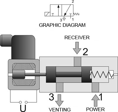
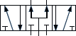
Graphic diagram of spool valve 3/2 controlled directly with the electromagnet , return by spring
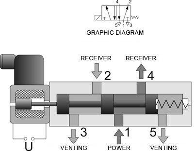
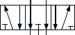
Graphic diagram of spool valve 5/2 controlled directly with the electromagnet , return by spring
The advantage of direct control is quick action valves, no contact working medium with the internal elements of the electromagnets and the simplicity of the design.
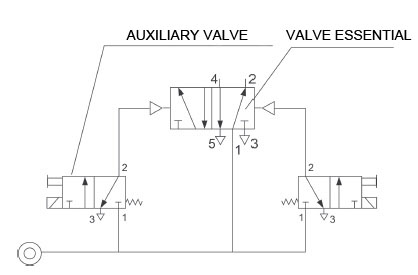
Pilot operated spool valves is carried out using an additional auxiliary valve is often referred to as 'pilot' (controlled in a direct manner), the electrical signal to the overload pressure of the working head on the active surface of the primary valve spool, causing the displacement. Normally it is used also additional mechanical control in the form of the auxiliary valve allowing the valve to stroke without giving an electrical signal.
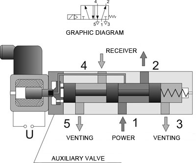
Graphic diagram of spool valve 5/2 controlled indirectly with the internal supply auxiliary valve channel 1.
Air pressure to override the auxiliary valve may be provided directly from the supply channel 1 liners made in the valve body or slider (called. Controlling self or internal pressure). It can also be administered externally via port in the valve or the subbase. Such control is called foreign control. After clipping the electrical signal of the auxiliary valve, the air pressure is applied to the surface of the slider, and the resulting force causes the movement and change of the internal connection flow paths. In order to increase the air pressure overload often can not be applied directly to the slide, but the additional piston with a larger diameter than the slider, and this only causes a movement of the slider. Such valves are called assisted pneumatic valves.
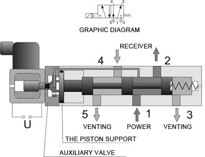
Graphic diagram of spool valve 5/2 controlled electrically with pneumatic support.
Cross-section of a typical spool valve controlled 5/2 electro-pneumatic back.
The return of the spool valve spool to its initial position caused by the forces is carried out:
- spring
- air pressure acting on the slider
- air pressure acting on the additional piston
- air pressure applied to the slider and the spring force.
The advantage is the ability to control intermediate valve control large flow volumes using a low power solenoids.
Power Method.
Because of the way the power spool valves are wired versions and labels. The valves have threaded holes wire supply, exhaust and receivers - made bodies. These are usually threads inch from G1 / 8 'to G3 / 4'. There are non-standard implementation of valves with other threads (metric, inch tapered, etc..)
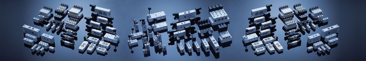
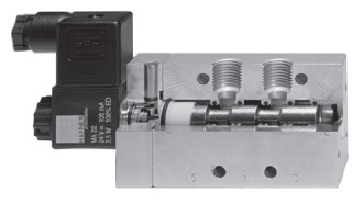
Plate valves are mounted through appropriate individual or valve plates composed of teams. Typically, plate valves have a high flow rate. Currently, commonly used valve islands consist of a large number of valves mounted on the disc, which offers an additional electrical connectors.
The advantages of plate solutions include:
- fast assembly and disassembly without removing the valve pneumatic system
- limiting the number of fasteners and wires
- possibility of installation in confined spaces
- integration of pneumatic control electronics
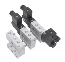
Modular valve terminal
1.2 Return valves
The check valve is used to achieve the working medium flow in only one direction, the opposite direction flow of the fluid is blocked. The valve operates automatically and does not require any additional signals. For the valve due to its construction it is essential minimum opening pressure, which should be as small as possible.
There is a variation of this type of valve called a controlled valve, wherein by introducing additional external signal may be the 'opening' for the working medium flow in the opposite direction.
1.3 Logic valves
Logic valves : sum and difference
These are valves used in pneumatic control systems and regulators to implement logic functions. The most commonly used product valves and valves sum, which allow the construction of pneumatic combinational and sequential.
1.4 Zawory odcinające
Electromagnetically-controlled shut-off valve
Group electromagnetically actuated valves, pneumatically and mechanically about the features of 2.2, 3.2 used for cutting and opening of roads flow. The working fluid can be compressed air, gases, steam, hydraulic oil or water. Sensitive is also an additional function: the valve normally closed (NC or called. NC) and normally open (NO), which is in what position the valve is no signal
2. Compressed air flow control valves
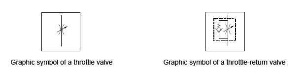
Flow control valves are used in pneumatic systems mainly for variable speed motion actuators (cylinders linear and rotary). To adjust the speed of movement of the piston rod are used throttle valves, check valves and throttle valves. Throttle – return valves allow for free movement of the working medium in one direction, and adjust throttling of the flow in the opposite direction. Throttle valves are bi-directional valves, throttling takes place in both directions of flow.
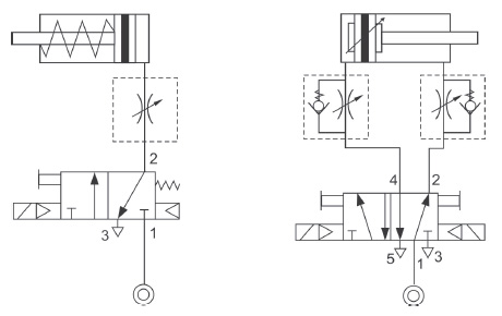
Examples of the use of flow control valves to regulate air traffic speed and double-rod cylinders single acting.
Due to the effectiveness of the choke return valves should be installed as close to the actuator due to the minimization of the volume of pollutants. Due to the compressibility of the working medium for the most efficient speed control cylinders is obtained choking the flow of air on the outlet side of the actuator chamber. It is used the movement speed of the cylinder in both directions or only in one direction.
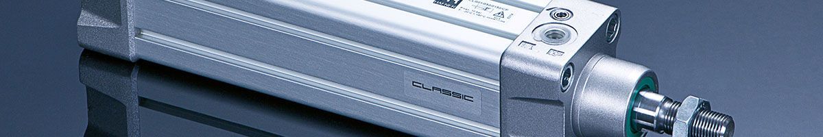
Elementy zamieniające energię sprężonego powietrza na energię mechaniczną - siłowniki pneumatyczne
The elements, which change the energy from the compressed air into mechanical energy – pneumatic cylinders
1. Basic information
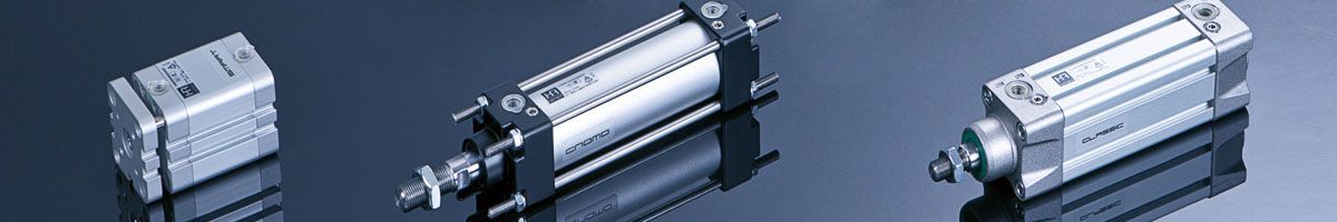
Pneumatic cylinders are pneumatic components which change the energy of compressed air into mechanical energy (force or torque) and pneumatic systems are a group of cylinders and are often used to drive machinery, equipment and supply control systems and automation of technological processes.
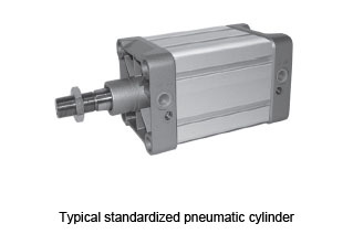
Due to the nature of the movement of the working (piston rod or shaft) cylinders are divided into:
- cylinders reciprocating piston rod
- cylinders with rotating shaft
In the group of cylinders of reciprocating motion variations thereof are as follows:
- piston cylinders
- immersion cylinders
- diaphragm cylinders
- bag cylinders (Tubed)
In the group of cylinders for rotary movement there are the following varieties:
- swing cylinders (carrying traffic in the range of 90°-360°)
- rotary cylinders (pneumatic motors)
- single acting cylinders
- double-acting cylinders
Diagrams on the following page illustrate the variety of the most common pneumatic cylinders and their graphical diagrams. Technical drawings of the pneumatic are permitted to use both schemes detailed and simplified.
| L.P. | Scheme | Description |
| 1 | Bilateral action pneumatic cylinder, pushing | |
| 2 | Bilateral action pneumatic cylinder, pulling with spring | |
| 3 | Unilateral action pneumatic cylinder with double piston rod, with bilaterally adjustable braking | |
| 4 | Unilateral action pneumatic cylinder with double piston rod, with bilaterally adjustable break and swipe piston position signalization | |
| 5 | Unilateral action pneumatic cylinder with double piston rod | |
| 6 | Unilateral action pneumatic cylinder with double and hollowed piston rod | |
| 7 | Rodless pneumatic cylinder with mechanical compression, bilaterally adjustable braking and swipe piston position signalization | |
| 8 | Four-position cylinder with swipe piston position signalization | |
| 9 | Pneumatic cylinder “tandem” with unilateral action with single piston rod and swipe piston position signalization |
2. Characteristics of typical piston pneumatic cylinders
2.1 Unilateral action cylinders
SPneumatic cylinders with a piston structure in which the movable element is a piston rod. The movement of the piston rod in both directions is performed by changing the energy of compressed air into mechanical energy fed into the cylinder chambers alternately.
he most common and widespread group of a executive element.
The cylinder can be equipped with one piston rod (cylinders with unilateral rod) or two (cylinders with two-sided piston rod). The basic parameter of the cylinder is its potency. The potency of a double-acting cylinder depends on the nominal diameter (D) and the supply pressure. Due to differences in the effective surface, above and below the piston, which operates the supply pressure below provides formulas for the calculation of the so-called pushing and pulling force of a double-acting pneumatic cylinder. These forces differ from each other
Usable force exerted of the double-acting cylinder is calculated from the following equations:
- for double-acting cylinder with single piston rod
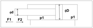
- p1 - supply pressure [bar]
- D-diameter nominal (piston) [cm]
- d - diameter of the piston rod [cm]
- The force pushing the cylinder F1: F1 = Π x D2 / 4 x p1 [kG]
- The tractive force cylinder F2 F2 = Π x (D2-d2) / 4 x p1 [kG]
- A pushing force of the cylinder with one-sided piston rod is greater than the pulling force
- for double-acting cylinder with the double piston rod
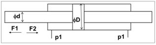
- p1 - supply pressure [bar]
- D-diameter nominal (piston) [cm]
- d - diameter of the piston rod [cm]
- The force pushing the cylinder F1 = Π x D2 / 4 x p1 [kg]
- The tractive force cylinder F2 = Π x (D2-d2) / 4 x p1 [kg]
2.2 Construction of double-acting cylinders
Construction of the pneumatic cylinder will be discussed based on standard cylinder compliant with ISO 6431 and VDMA 24562
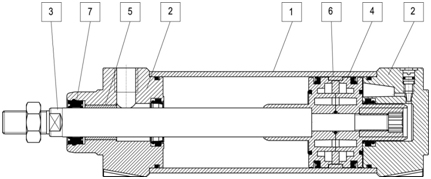
A typical double-acting pneumatic cylinder is composed of the following structural elements:
1 - cylinder sleeve
2 - Covers the cylinder (front and back)
3 - piston rod
4 - piston with seals and magnet
5 - piston rod bushing
6 - piston guide ring
7 - Seal piston rod with a scraper.
Basic technical parameters describing the pneumatic cylinders:
- pneumatic cylinder diameter from 8 mm to 320 mm (larger diameters are regarded as unusual)
- stroke range from 1 mm to approx. 3,000 mm (due to the availability of the sleeve)
- forces useful when running a standard pressure 0,63MPa of 5 daN up to 5000 daN
- operating pressure of 0.05 MPa to 1.6 MPa
- operating temperature range from -20 to + 180 ° C (depending on seals used)
- working medium - compressed air to clean the min. 40 microns, oil mist lubricated or non-lubricated air cleaned (requires accurate filtration of about 20 microns)
require confirmation of the duty cycle drives is required, the cylinder is used with magnet built into the piston. This allows for contactless proximity sensors. These are the components that use a magnetic field to generate electrical signals representing information on the state of the object in the control and regulation systems. Sensors are used reed or electronic (semiconductor) mounted directly on the cylinder or sleeve shaped using the appropriate brackets. This type of signaling is called the sensing piston position.
There are also solutions, where signaling and in particular to confirm the working traffic enforcement inductive sensors are used.
Due to the different in the working environment of pneumatic cylinders, load and place of character of their construction , different materials have to be used. The typical varieties of pneumatic cylinders include:
● Cylinders operating in particularly difficult environments exposed to corrosive substances, fresh water and seawater, agents and food products, operating in an explosive atmosphere. Basic industries using this type of cylinders are: food, chemical and pharmaceutical industries, devices operating on vessels and aviation, defense industry.
The cylinders can be entirely made of stainless steel or steel. For economic reasons, often only some of the most vulnerable to adverse conditions Cylinder parts are made of quality steel (rod bushings, tie bolts, nuts).
● Performed by a plastic cylinders.
The conditions identical to those listed above, the most commonly performed plastic bushings and cylinder cover.
● Cylinders for low or high temperatures
In this type of varieties of cylinders, special seals capable of withstanding extremely high or low ambient temperatures including extreme climatic conditions. The most common used seal material is Viton (a type of synthetic rubber) and Teflon. Basic industries using this type of cylinders are: food industry (cold), cryogenics, iron and non-ferrous metals, heat treatment and surface treatment of metals, molding, railways, military vehicles, vehicles for road building, factories bitumen.
● Cylinders with steel covers and sleeves. These cylinders are designed to be particularly difficult working conditions, where there is a risk of mechanical damage to the drive, the cylinders working in dusty and explosive atmosphere. They are used in coal mining, oil and gas, offshore, steel mills, construction and road.
● Cylinders special and unusual.
Type of pneumatic drives dedicated to specific solutions, machinery and equipment. Cylinders of this type are produced for specific customers with unusual requirements for the overall dimensions, design solutions, applied seals or cylinder is equipped with additional accessories such as external. Spool valves, valves to control the speed of movement of the piston rod, etc. Pneumatic cushioning.
Pneumatic cylinders are characterized by high speed movement of the piston rod. This translates into a kinetic energy, which may result in direct contact with the surface of the piston cover. In order to protect the internal components cylinders equipped with a cushioning acting on a cushion of air generated between the surfaces of the piston and the cover. Cushioning is adjustable throttle valve.
2.3 Pneumatic unilateral action.
Single-acting cylinders traversed working by giving pressure to the working chamber, the return movement of the cylinder is performed by external forces. These forces come usually mounted springs. In the single-action return movement can cause the force from the weight of the installed load.
2.4 Standard cylinders.
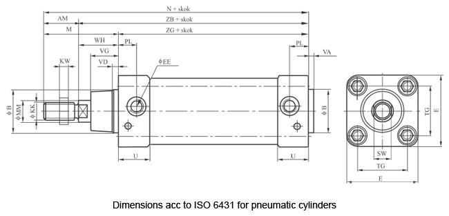
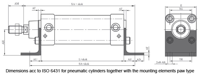
Pneumatic cylinders as one of the few groups of pneumatic components has a number of standards for their overall dimensions. Nowaday standard cylinders are widely used, as that allow for full interchangeability drives from different manufacturers.
One of the first standards for pneumatic cylinders prevalent in the world have become standard ISO6431 and ISO6432. These standards include not only the overall dimensions of the cylinders with diameters from 8 mm to 320 mm, but also the dimensions of the cylinder with the mounting element.
Below is an example of drawing with dimensions by ISO standards 6431st The letter dimensions are universal and used by manufacturers of pneumatic cylinders in the catalogue. These standards are currently being replaced by ISO 15552, which also includes the implementation of the cylinder sleeve the profile of channels for proximity sensors.
Wytwarzanie sprężonego powietrza
Manufacturing of the compressed air
The compressed air is produced by compressors. The compressor is a device, which increases the pressure of the working medium above the starting pressure – which is said to be the atmospheric pressure. According to the definition and compressor’s construction features, compressors can be divided into two groups:
- Positive displacement compressors
- Flow compressors.
In the positive displacement compressors the pressure increase is by suction and pressing the gas volume in the form of successive portions of the item in part driven. Compression of the air is done in the enclosed volume. Due to the type movement which is executed by the displacement element, the compressor can be divided into:
- sliding-return motion compressors (piston)
- rotary motion compressors (vane, toothed, rotary).
Please see below, the most common types of compressors
1. Piston compressors
It is one of the most common groups of the compressors used to make the compressed air in the industrial installations. They are dedicated to produce the output pressures in the range from 0,1 MPa (1 bar) up to more than a dozen MPa (tens of bar).
Mobility element of these compressors is the driven piston which does the sliding- return motion and thanks to it , it draws the atmospheric air, compresses it and then sends to the stamping area. The construction of the piston compressor is given below:
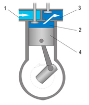
1 - suction chamber
2 - working chamber
3 - stamping area
4 - piston
2. Positive displacement – diaphragm compressors
Diaphragm compressors, are also called diaphragm flaps. They are equipped with a moving piston, which moves diaphragm air compression. It is separated from the compression chamber. There is no direct contact with the compressed air, thus it is not contaminated with the oil used to lubricate the piston. These compressors are used where very high grade of air purity is required- for example: pharmaceutical industry, food industry chemical industry, etc. The construction of the compressor is shown in the following diagram:
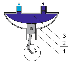
1 - Piston
2 - Diaphragm
3 - Compression chamber
3. Rotary displacement compressors
Rotary displacement compressors are classified according to the number of shafts. There are compressors with one shaft, two shafts or more shafts. The operating principle of rotary compressors is compressed portion of the gas in the working areas of variable volume. Rotary Displacement compressors are divided into:
- screw compressors
- vane compressors
- Root’s compressors
- compressors with rotary piston
- compressors with water ring
4. Rotary screw compressors
The rotary screw compressors are devices, that are dedicated for producing compressed air on the two rotating shafts. Rollers have a profile with screws and are asymmetric one to another. The principle of operation is based on the formation of the inner chambers, wherein the compression of air between the two rotors is screw-shaped. The air in the chamber moves from the suction side to the discharge channel.
The main advantages of screw compressors are:
- high performance
- the absence of the flow and pressure pulsations
- ability to work in 24h
- constant flow and pressure at the outlet
- thermal energy recovery
- quiet operation
- Full control over parameters and working time
- low power consumption
- through the formation of an oil film between cooperating rotors there is no direct contact area, which increases the durability of the device
The figure below shows the principle of a screw compressor
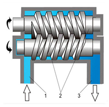
1 - Inlet channel
2 - asymmetrical screw rotors
3 - channel pumping
Screw team
5. Root’s compressors – centrifugal
This compressors fulfills the role of elements of the two motors driven by the rotor profile. A characteristic of this type of compressor is that the air moves from the inlet to the outlet without a change in volume. Working space has the shape of cooperating cam-shaped rotor, the space on the inlet side is increased to allow air suction. From the pressure side decreases in volume to compress the air. The diagram below shows the construction of the compressor.
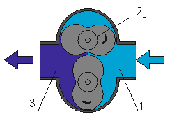
1 - suction chamber
2 - shaped rotors
3 - pumping chamber
6. Reciprocating displacement vane
A compressor, wherein the pressure increase takes place in the shrinking chamber as a space formed between the slidably mounted on the rotor blades and the compressor housing. The axis of rotor blades is mounted eccentrically offset relative to the axis of the body. During the movement of the rotor blades centrifugal force presses the sides of the body sealing working chambers, which, together with the trade to reduce its volume compress air discharge side. The increasing displacement from the suction side allows air intake. The following diagram illustrates the operation of the compressor vane.
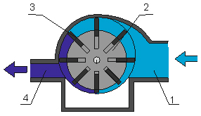
1 - suction channel
2 - eccentric rotor
3 - movable vanes
4 - channel virgin
The biggest advantages of vane compressors:
- quiet, devoid of emotion work
- high purity of the obtained compressed air
- simple, easy to repair and maintenance construction
- the possibility of continuous operation in cycles of 24 hours at a stabilized temperature
- lack of ball bearings, which can generate noise and are subject to wear
7. Screw flow compressor
Compressors working on the principle of flow of the air flow and their construction are used in the systems or devices requiring a very high flow rate (expense). They are characterized by the relatively low pressure at the outlet. Air compressor element is rotating at a high speed rotor, which causes the geometry of the vacuum from the suction air. Screw flow compressors are divided into two groups: the turbocharger, wherein the movable member is shaped rotor blades and the jet compressor.
Przygotowanie sprężonego powietrza
Preparation of compressed air
1. Basic information
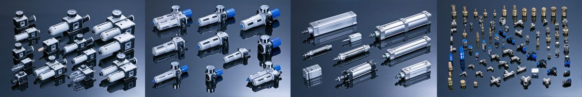
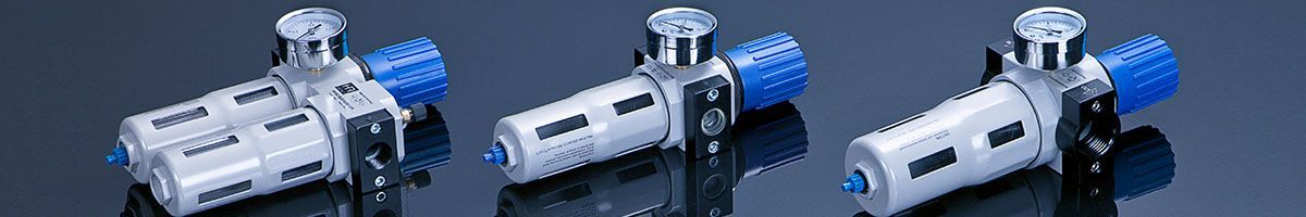
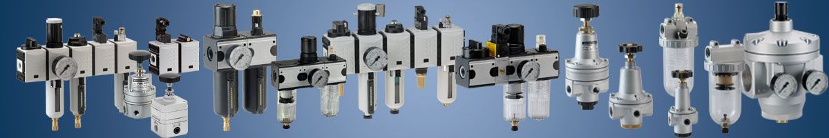
The first pneumatic elements are located directly after compressors and are the air preparation units elements. They are used to prepare the working medium, necessary for the proper operation of pneumatic components:
- clearing - (filtration) from the solid particles, particles of oil condensate water - filter
- reduction (adjusting) pressure to the required level of working - pressure-reducing valves
- covering with mist - lubricators.
Preparation of compressed air is carried out to enhance the stability of pneumatic components, extending the service life of the controls and regulations. Reduction of component failure is achieved by lubrication of the moving parts and sealing:
Particulates - entering the compressed air through the compressor to the intake air from the environment. They remain in the devices of compressed air (as well as pipes and installations). These particles are released through physic-chemical (corrosion, scale, particle aging and damaged seals) or mechanical due to wear of moving parts in the compressor or other pneumatic components included in the system.
Oil - coming from the compressor (mainly the construction of the piston), or in the form of debris, entrained by the air flow from the walls of the ducts. The oil in the form of droplets may also precipitate in the form of condensate in the case of intentional pneumatic lubrication oil mist.
Water - in a natural manner is dissolved in the form of water vapor sucked in through the outside air compressor. Water can also enter the compressed air tanks are placed for the compressors. The amount of water contained in the working medium of the air temperature and relative humidity.
2. Methods
2.1 Filtration
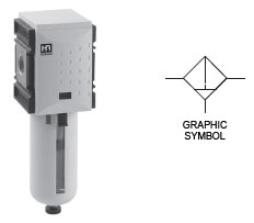
Filtration of the compressed air takes place in a filter that removes particles primarily. They are filtered by the filter element with the specified accuracy of purification. As the standard of cleaning shall be 40 µm, which is equivalent to 5th grade purity compressed air and it is sufficient for the correct operation of pneumatic fittings. In the case of precision pneumatic components filtration accuracy should be 5µm, which, according to ISO 8573-1: 2010, is the 3 air cleanliness class. Standard filters also remove precipitated by expanding the working fluid in liquid water. They also remove larger particles of oil. Thanks to the centrifugal force of whirling stream, bigger participles are disposed on the inner surface of the tanks. Below is a table with compressed air quality classes.
| Class according to ISO 8573-1 | The maximum size of particles [µm] | The maximum concentration of particles [mg/m²] | The maximum value of the pressure dew point [°C] | The maximum oil concentration [mg/m²] | The maximum content of H2O [g/m³] |
| I | 0,1 | 0,1 | -70 | 0,01 | 0,003 |
| II | 1 | 1 | -40 | 0,1 | 0,12 |
| III | 5 | 5 | -20 | 1 | 0,88 |
| IV | 15 | 8 | +3 | 5 | 6,0 |
| V | 40 | 10 | +7 | 25 | 7,75 |
| VI | +10 | 9,4 |
The figure below shows the construction of a typical filter used for rough air purification.
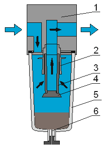
The filter is made from the body (1) which is built into the holes - the power and exhaust. Air enters the filter in accordance with the arrows and is directed downwards, where the drive (2) causes swirling air stream and expands, thus precipitating the water contained in the air. The centrifugal force throws the walls of the tank (5) higher suspended solids (oil condensate droplets, water droplets, particles) that accumulate on the bottom of the tank in the form of condensate. The air flows through the cartridge filtering (3), and is treated with minor impurities (in Dependency on the accuracy of filtering). Is then directed to the outlet and downstream parts of the system. Filters are equipped condensate discharge valves(6), which can operate manually, semi-automatically or automatically.
In order to protect the tank against mechanical damage, mounting the cover is recommended.
Manual releases are activated by screwing or pressing the stopper. Semi-automatic vent valves utilize the pressure drop across the valve element for opening and ejecting the condensate. Fully automatic drains are equipped with a float valve which is being opened when the target level of condensate in the tank is exceeded.
In accordance with the applicable provisions of the condensate is drained from the filters, oil molecules must be subjected to a purification process before being discharged to the sewer.
2.2 Oil separation
The oil contained in the working medium is removed in an oil separator. The condensate oil and water may also be removed to some extent in the filters, but it is not a complete removal. Oil free operating medium is particularly important in some industries, such as food, pharmaceutical, varnishing and medicine. It is also not a desirable in precision industrial automation systems.
Further purification steps of compressed air :
- Pre-filtering the air through filters - traps in which the separation of the oil droplets by centrifugal precipitation of the walls of the device. This method allows you to clean the air only with large concentrations of oil particles.
- Filtration with a first-class cleanliness.
- Filtration with activated carbon filters.
In order to optimize operating costs of precision oil separators should be installed in front of them coarse filters.
2.3 Drainage of the working medium
Preliminary and necessary for the proper operation of components and systems, pneumatic removal of water is done by filters. Precise removal of water from the working medium, which is required in some applications is accomplished through dehumidifiers, which use physical and chemical phenomena. (dryers, cyclones, absorption, Refrigeration).
This phase is the biggest contributor to ensuring a level of preparedness adeqately working medium. Precipitating water in the pneumatic systems is the cause of many disturbances and failures. The following are the most important reasons for failure:
- Corrosion causing secondary pollution principles permanent and debilitating design and installation of pneumatic equipment,
- Reducing the active section of the channels in the elements of air and increasing the air friction of the corroded surface,
- Leaching of solid lubricants with moving parts, pneumatic equipment causing the excessive wear or failures.
In addition to the use of specialized equipment to remove water, you can already at the stage of system design avoid excessive accumulation of water. Below are some practical methods:
- Pneumatic systems should be performed at a small angle rising, so that condensed water running down to the lowest point, there will be discharged to the outside. ,
- Departures (pions) from the main system should be operated only from the top of the power cord, which prevents the already precipitated condensate receivers,
- Use traps cyclone not only for the compressor or air tank, but also against any receiver,
- Use high pressure reductions compared to the supply pressure.
2.4 Reduction (adjustable) pressure working medium

The regulator compressed air
To reduce the pressure in the pneumatic systems to the required level applies pressure reducers. These valves belonging to the group of elements pneumatic control pressure (usually adjustable manually), whose task is to maintain a constant pressure of the working medium at the output, regardless of changes in the higher inlet pressure regardless of changes in the rate of flow through the valve.
Elements of reducing pressure to the required level are divided into the following groups:
- Direct action
- Second control pressure:
- The internal pressure of the reference ,
- The internal pressure of the reference,
- Components:
- With solenoid valves ,
- Piezo valves
Below is a diagram of a typical pressure-reducing valve spring structure.
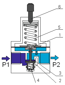
The operating principle is based on cutting off the supply chamber, in which there is a supply pressure P1 from chamber starting with the poppet valve (2) closing the valve seat (3). The armature is at the top, through a force of the pusher spring (5) tensioned by rotation of the adjusting screw. Poppet valve without shutoff of this force is the force of the spring into the slot (4). Realizing valve opening by downward movement of the diaphragm assembly and causes air to flow into the output chamber (for a poppet valve) and increase the pressure P2 in the chamber to a value dependent on the strength of the spring tension. The output pressure is also supplied to the chamber beneath the membrane (1). The increase in pressure P2 increases the force counteracting the force of the opening spring valve, until its closure, or the establishment of such an intermediate position at which the output pressure will stabilize and the balance force of the spring adjusting. Tight the control spring (5) using the screw (6) to change the valve opening force, which shall be submitted on change in the value of reduced output pressure P2. By reducing the pressure to atmospheric pressure the valve vents the excess pressure drops to atmospheric. P2 pressure at the outlet of the valve does not change when changing the supply pressure P1. The catalogs for pressure reducing valves are always served operating characteristics: regulatory and flow. Regulatory characteristics determines the output pressure changes in relation to the inlet pressure and flow rate determines the air flow through the valve at a predetermined pressure drop reduced value P2.
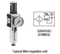
Commonly used a single unit of two components: the filter and the pressure reducing valve. This element is called band filter-regulator or valve-filter. This is the first element where the air is cleaned and then the cleaned air flows into the pressure reducing valve, where the pressure reduction to the working pressure.
2.5 Lubrication of the compressed air
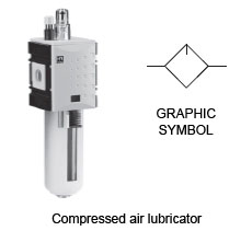
In the pneumatic systems there are elements, that are responsible for forming the friction kinematic pairs (eg. Piston - sleeve, piston rod - guide sleeve in the pneumatic cylinder). To make sure that the device operates correctly it must be lubricated with oil. Lubricated air is also required for pneumatic tools such as hammers, drills, screwdrivers, grinders, where all elements move at very high speeds and are driven by pneumatic turbines.
Lubrication of the compressed air is the introduction to the working medium of oil particles in the form of mist, which reached to the cylinders and control lubrication of the moving parts. This prevents faults and failures, further prolonging their service life and reducing the incidence of corrosion. Generating elements are oil mist lubricators compressed air. In modern construction solutions used seals made of polyurethane (PU).Cylinders with seals of this material do not require lubrication with oil mist.
Lubricators, because of their structure are divided into the following groups:
- drinkers,
- selection,
- wick,
- injection,
- vesicular.
The most common are the nipple lubricators.
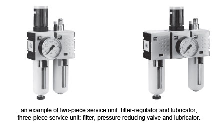
Their principle is based on the phenomenon of drop in pressure in the lubricator gun nozzle, which draws a drop of oil from the reservoir through the tube, droplet chamber, where oil droplets are broken up into a stream of compressed air and oil mist then introduced into the pneumatic system. These elements of the air preparation system appears individually, or more frequently as air preparation units or power stations. Then they consist of two or three components:
- two-piece service unit: filter-regulator and lubricator,
- three-piece service unit: filter, pressure reducing valve and lubricator.
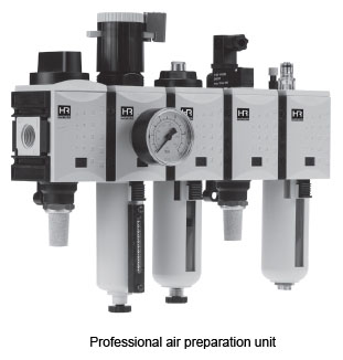
Professional air preparation units are understood as a complex elements of air preparation units which may include additional equipment needed to supply the modern pneumatic systems. These can be manually controlled shut-off valves or solenoids, valves slow start (the so-called. Soft-start), pneumo-electric relays, pressure gauges, flow meters and pressure displays and outputs for drivers. This results in extending the functionality of a typical air handling units.
Charakterysyka medium roboczego
Characteristic of the working medium
1m3 of atmospheric air contains:
- 140 mln pollution participles, which equals on average from 0,005 up to 0,020 g/m3 and in the particulary dusty regions even up to 0,1 g/m3,
- 10 mg of oil,
- About 11g of steam.
According to above features it has to be specially prepared in order to be used in the pneumatic systems and drives. The professional preparation of compressed air consist of:
- all solid and liquid contaminants,
- reducing pressure to the required value,
- making lubrication for devices that require it..
Properties of cleared and correctly prepared compressed air:
- Lack of water as drops of water, water as steam is permitted, only on condition when the dew point occurs at the temperature for 5-10°C lower that the lowest operating temperature of the system,
- Occurrence of mechanical contaminants of principle size above 10µm,
- Absence of oil as drops.
Advantages and disadvantages of compressed air as a working medium
Pneumatics as a branch of science is being used so widely, because of the type of working medium. It has a lot of advantages , which are listed below :
- common and almost unlimited availability of renewable working medium
- low viscosity, which guarantees low flow residence, which enables you to design propulsion systems with high-speed line (to 30m/s),
- damps the variation,
- it gives you the possibility of stepless operation of pneumatic drives:
- speed linear and rotary of pneumatic drives are moved by adjusting the flow rate of the working medium,
- orces and moments useful cylinders by adjusting the pressure of the working medium - low sensitivity and resistance to changing load - overload drive is stopped
- high durability and easy operation of elements of the compressed air in a wide rang
- of operating temperatures at a relatively low cost of use and operation,
- no need for discharge lines working medium,
- resistance to the influence of external electromagnetic fields
- air is a medium that is safe, clean and ecological in operation –there is no danger of electrocution and does not pollute the environment even in the case of the system damage,
- compressed air is easy to transport over long distances wires and also it is easy to be stored.
According to compressed air features, it has some disadvantages, which are listed below:
- it has to be cleared from solid and liquid contaminants,
- during the air pressure change, as well as when changing its temperaturę,the water is precipitated,
- compressibility of working medium (air) is about 2000 times higher than the hydraulic oil compressibility
- positioning and simultaneous movement of the drive's elements
- limiting the scope of useful forces and moments generated by the operating pressures (up to 10 bars)
- limited length of the linear motion due to the technical possibilities of stroke
- high costs of manufacturing the working medium and the possibility of leaks in the circuit transmitting working medium.
The Design Departament

General Pneumatics

A Reliable company

General trade conditions

ABOUT US
Pomagier-Trzebuchowscy
sp. z o.o.
ul. Marii Skłodowskiej-Curie 97
87-100 Toruń
NIP 556-22-23-819
Regon 092307860
KRS 0000154149
Santander Bank Polska SA
79 10901069 0000 0000 0704 8941
Bank account ING Bank Śląski
64 10501139 1000 0023 4975 0618
CSP
Fundusz Europejski

News
We have become part of the Rubix Group
Hafner w czasie pandemii

Generatory azotu

Siłowniki dla hutnictwa
CSP

Cylinders production