

")

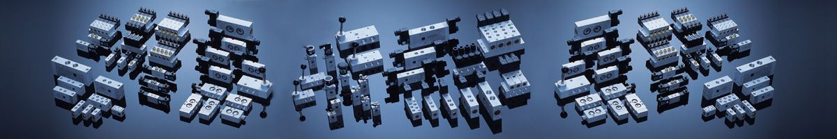
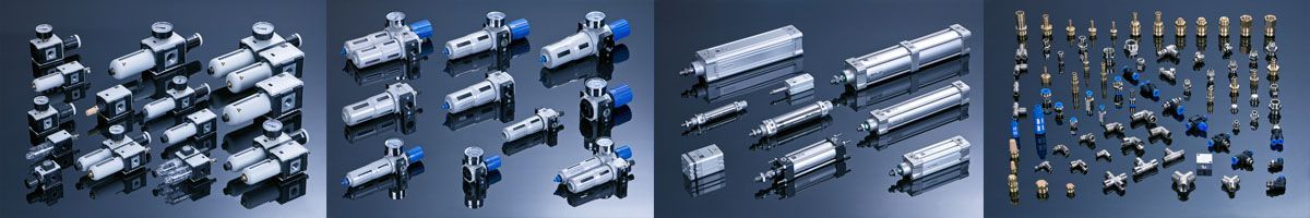
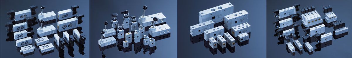
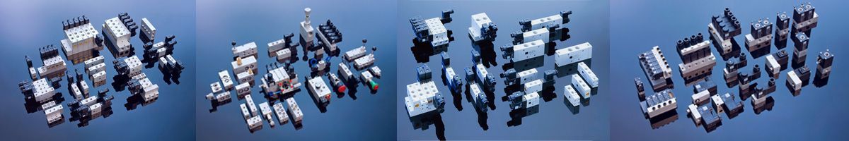
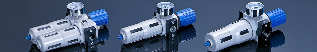

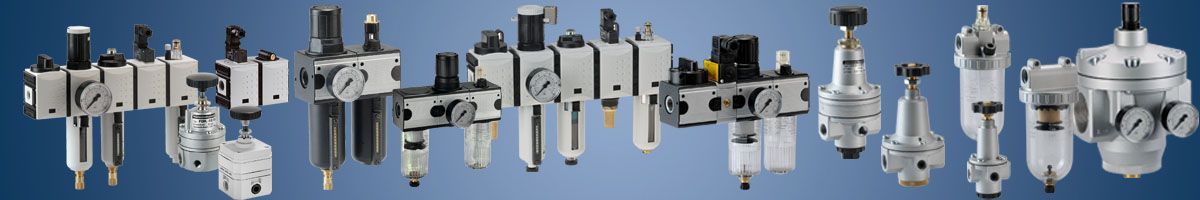

Pneumatics, Compressors, Dryers, Tanks, Pneumatic installations, Air prepration units, Gauges, Pneumatic tubes, Pneumatic valves, Pneumatic cylinders, Pneumatic fittings.
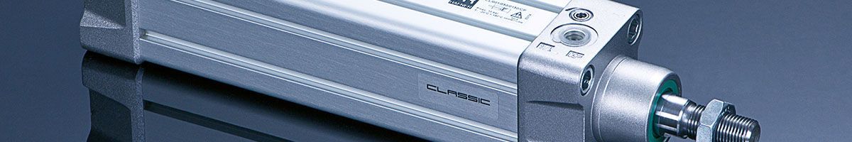
The elements, which change the energy from the compressed air into mechanical energy – pneumatic cylinders
1. Basic information
Pneumatic cylinders are pneumatic components which change the energy of compressed air into mechanical energy (force or torque) and pneumatic systems are a group of cylinders and are often used to drive machinery, equipment and supply control systems and automation of technological processes.
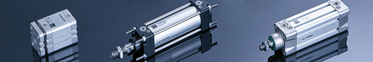
Due to the nature of the movement of the working (piston rod or shaft) cylinders are divided into:
- cylinders reciprocating piston rod
- cylinders with rotating shaft
In the group of cylinders of reciprocating motion variations thereof are as follows:
- piston cylinders
- immersion cylinders
- diaphragm cylinders
- bag cylinders (Tubed)
In the group of cylinders for rotary movement there are the following varieties:
- swing cylinders (carrying traffic in the range of 90°-360°)
- rotary cylinders (pneumatic motors)
- single acting cylinders
- double-acting cylinders
Diagrams on the following page illustrate the variety of the most common pneumatic cylinders and their graphical diagrams. Technical drawings of the pneumatic are permitted to use both schemes detailed and simplified.
| L.P. | Scheme | Description |
| 1 | Bilateral action pneumatic cylinder, pushing | |
| 2 | Bilateral action pneumatic cylinder, pulling with spring | |
| 3 | Unilateral action pneumatic cylinder with double piston rod, with bilaterally adjustable braking | |
| 4 | Unilateral action pneumatic cylinder with double piston rod, with bilaterally adjustable break and swipe piston position signalization | |
| 5 | Unilateral action pneumatic cylinder with double piston rod | |
| 6 | Unilateral action pneumatic cylinder with double and hollowed piston rod | |
| 7 | Rodless pneumatic cylinder with mechanical compression, bilaterally adjustable braking and swipe piston position signalization | |
| 8 | Four-position cylinder with swipe piston position signalization | |
| 9 | Pneumatic cylinder “tandem” with unilateral action with single piston rod and swipe piston position signalization |
2. Characteristics of typical piston pneumatic cylinders
2.1 Unilateral action cylinders
SPneumatic cylinders with a piston structure in which the movable element is a piston rod. The movement of the piston rod in both directions is performed by changing the energy of compressed air into mechanical energy fed into the cylinder chambers alternately.
he most common and widespread group of a executive element.
The cylinder can be equipped with one piston rod (cylinders with unilateral rod) or two (cylinders with two-sided piston rod). The basic parameter of the cylinder is its potency. The potency of a double-acting cylinder depends on the nominal diameter (D) and the supply pressure. Due to differences in the effective surface, above and below the piston, which operates the supply pressure below provides formulas for the calculation of the so-called pushing and pulling force of a double-acting pneumatic cylinder. These forces differ from each other
Usable force exerted of the double-acting cylinder is calculated from the following equations:
- for double-acting cylinder with single piston rod
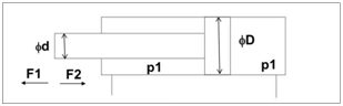
- p1 - supply pressure [bar]
- D-diameter nominal (piston) [cm]
- d - diameter of the piston rod [cm]
- The force pushing the cylinder F1: F1 = Π x D2 / 4 x p1 [kG]
- The tractive force cylinder F2 F2 = Π x (D2-d2) / 4 x p1 [kG]
- A pushing force of the cylinder with one-sided piston rod is greater than the pulling force
- for double-acting cylinder with the double piston rod
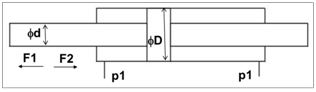
- p1 - supply pressure [bar]
- D-diameter nominal (piston) [cm]
- d - diameter of the piston rod [cm]
- The force pushing the cylinder F1 = Π x D2 / 4 x p1 [kg]
- The tractive force cylinder F2 = Π x (D2-d2) / 4 x p1 [kg]
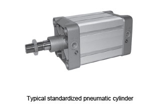
2.2 Construction of double-acting cylinders
Construction of the pneumatic cylinder will be discussed based on standard cylinder compliant with ISO 6431 and VDMA 24562
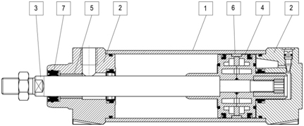
A typical double-acting pneumatic cylinder is composed of the following structural elements:
1 - cylinder sleeve
2 - Covers the cylinder (front and back)
3 - piston rod
4 - piston with seals and magnet
5 - piston rod bushing
6 - piston guide ring
7 - Seal piston rod with a scraper.
Basic technical parameters describing the pneumatic cylinders:
- pneumatic cylinder diameter from 8 mm to 320 mm (larger diameters are regarded as unusual)
- stroke range from 1 mm to approx. 3,000 mm (due to the availability of the sleeve)
- forces useful when running a standard pressure 0,63MPa of 5 daN up to 5000 daN
- operating pressure of 0.05 MPa to 1.6 MPa
- operating temperature range from -20 to + 180 ° C (depending on seals used)
- working medium - compressed air to clean the min. 40 microns, oil mist lubricated or non-lubricated air cleaned (requires accurate filtration of about 20 microns)
require confirmation of the duty cycle drives is required, the cylinder is used with magnet built into the piston. This allows for contactless proximity sensors. These are the components that use a magnetic field to generate electrical signals representing information on the state of the object in the control and regulation systems. Sensors are used reed or electronic (semiconductor) mounted directly on the cylinder or sleeve shaped using the appropriate brackets. This type of signaling is called the sensing piston position.
There are also solutions, where signaling and in particular to confirm the working traffic enforcement inductive sensors are used.
Due to the different in the working environment of pneumatic cylinders, load and place of character of their construction , different materials have to be used. The typical varieties of pneumatic cylinders include:
● Cylinders operating in particularly difficult environments exposed to corrosive substances, fresh water and seawater, agents and food products, operating in an explosive atmosphere. Basic industries using this type of cylinders are: food, chemical and pharmaceutical industries, devices operating on vessels and aviation, defense industry.
The cylinders can be entirely made of stainless steel or steel. For economic reasons, often only some of the most vulnerable to adverse conditions Cylinder parts are made of quality steel (rod bushings, tie bolts, nuts).
● Performed by a plastic cylinders.
The conditions identical to those listed above, the most commonly performed plastic bushings and cylinder cover.
● Cylinders for low or high temperatures
In this type of varieties of cylinders, special seals capable of withstanding extremely high or low ambient temperatures including extreme climatic conditions. The most common used seal material is Viton (a type of synthetic rubber) and Teflon. Basic industries using this type of cylinders are: food industry (cold), cryogenics, iron and non-ferrous metals, heat treatment and surface treatment of metals, molding, railways, military vehicles, vehicles for road building, factories bitumen.
● Cylinders with steel covers and sleeves. These cylinders are designed to be particularly difficult working conditions, where there is a risk of mechanical damage to the drive, the cylinders working in dusty and explosive atmosphere. They are used in coal mining, oil and gas, offshore, steel mills, construction and road.
● Cylinders special and unusual.
Type of pneumatic drives dedicated to specific solutions, machinery and equipment. Cylinders of this type are produced for specific customers with unusual requirements for the overall dimensions, design solutions, applied seals or cylinder is equipped with additional accessories such as external. Spool valves, valves to control the speed of movement of the piston rod, etc. Pneumatic cushioning.
Pneumatic cylinders are characterized by high speed movement of the piston rod. This translates into a kinetic energy, which may result in direct contact with the surface of the piston cover. In order to protect the internal components cylinders equipped with a cushioning acting on a cushion of air generated between the surfaces of the piston and the cover. Cushioning is adjustable throttle valve.
2.3 Pneumatic unilateral action.
Single-acting cylinders traversed working by giving pressure to the working chamber, the return movement of the cylinder is performed by external forces. These forces come usually mounted springs. In the single-action return movement can cause the force from the weight of the installed load.
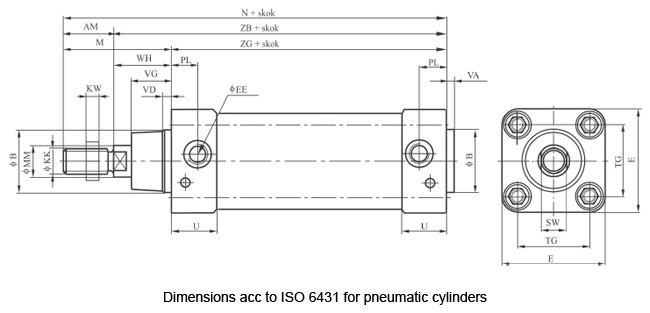
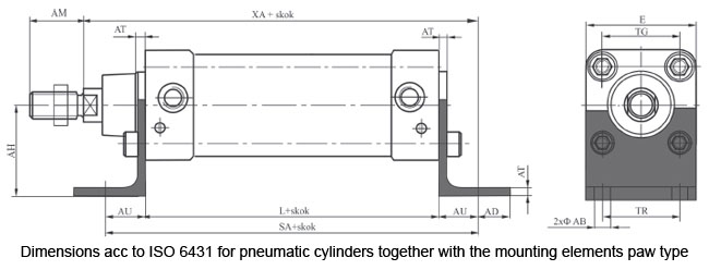
2.4 Standard cylinders.
Pneumatic cylinders as one of the few groups of pneumatic components has a number of standards for their overall dimensions. Nowaday standard cylinders are widely used, as that allow for full interchangeability drives from different manufacturers.
One of the first standards for pneumatic cylinders prevalent in the world have become standard ISO6431 and ISO6432. These standards include not only the overall dimensions of the cylinders with diameters from 8 mm to 320 mm, but also the dimensions of the cylinder with the mounting element.
Below is an example of drawing with dimensions by ISO standards 6431st The letter dimensions are universal and used by manufacturers of pneumatic cylinders in the catalogue. These standards are currently being replaced by ISO 15552, which also includes the implementation of the cylinder sleeve the profile of channels for proximity sensors.
The Design Departament

General Pneumatics

A Reliable company

General trade conditions

ABOUT US
Pomagier-Trzebuchowscy
sp. z o.o.
ul. Marii Skłodowskiej-Curie 97
87-100 Toruń
NIP 556-22-23-819
Regon 092307860
KRS 0000154149
Santander Bank Polska SA
79 10901069 0000 0000 0704 8941
Bank account ING Bank Śląski
64 10501139 1000 0023 4975 0618
CSP
Fundusz Europejski

News
We have become part of the Rubix Group
Hafner w czasie pandemii

Generatory azotu

Siłowniki dla hutnictwa
CSP

Cylinders production